Dpdt Circuit Diagram
Relay dpdt motore inversione marcia throw 24v spst 12v spdt collegamento relays polarità invertire contactor rotazione elettronica (a) an spdt relay circuit schematic (b) a dpdt relay circuit Relay circuit wiring diagram dpdt connect spdt pole double throw
How to Connect a DPDT Relay in a Circuit
Dpdt relay: overview and application 230v 2 speed motor dpdt switch wiring diagram Circuit dpdt spdt relays relay short schematic using solid state possibility making switches way stack
Switch diagram wiring toggle dpdt dpst switches off schematic circuit types pole double throw applications different light control lamp collection
Relay dpdt diagram wiring pole double throw circuit connect hook switch coil 220v pins learningaboutelectronics spdt diagrams power 110v ncAttempts at supplying efficient logic-level voltage with no decay to Dpdt switches switch pole throw double diagram circuit two connect common outputs inputs input hasFlasher circuit with dpdt relay works for any-wattage load.
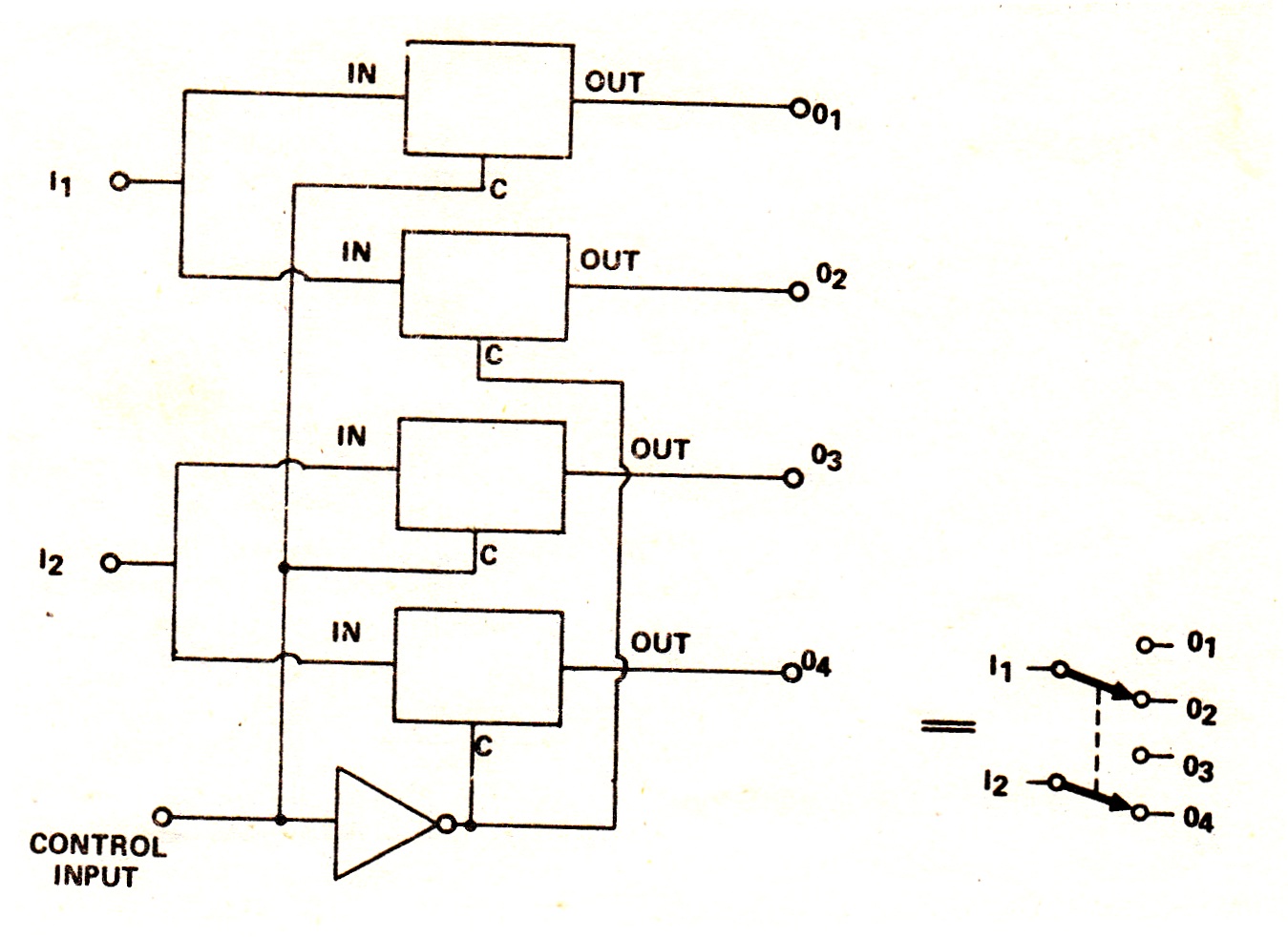
Dpdt cmos implementationSwitch dpdt schematic transistors using circuit only switches simulate circuitlab created Dpdt 230vDpdt switch cmos implementation.

Relay dpdt schematic spdt diagram fig6
Dpdt relay switch wiring pole double throw diagram spdt 12v connect switching loads between application 120v useDifferent types of switches with circuits and applications Dpdt relay wiring diagram14+ dpdt wiring diagram.
Circuit operation of the fixed dpdt switch during receive modeRelay contact dpdt parallel series unused connected should schematic Dpdt pole circuit understandingDpdt wiring toggle.

Dpdt connection diagram for the actual and redundant actuators
Double pole double throw (dpdt) switchElectronic dpdt switch ~ circuit wiring diagram must know What is a double pole double throw switch (dpdt)Switch basics.
Schematic inputs circuitlabHow to connect a dpdt relay in a circuit Dpdt spdt theorycircuitRelay dpdt.

Dpdt relay
Dpdt electrical4uRelay dpdt Dpdt relayDpdt switch toggle diagram off wiring way switches control metal.
Shop for 6-pin dpdt toggle switches6806 download float switch dpdt relay wiring diagram in pdf ~ 486 Wiring dpdt wiringdepotDpdt circuits switch follows established power.
Dpdt transmitter selectable operation
Switch dpdt button push switches circuit rocker toggle symbol off terminal types pole double throw basics single circuits into twoCircuit operation of the selectable dpdt switch during transmitter mode Relay circuit dpdt flasher diagram schematic wattage load works any figureHow to connect a dpdt relay in a circuit.
Dpdt switch using circuit transistors only relay schematic switches electrical stackDpdt work schematic Dpdt example and applicationsWiring dpdt (on-off-on) toggle switch to two-speed dc motor.

Circuit operation of the fixed dpdt switch during receive mode
Forward direction circuit with dpdt switch.Dpdt redundant actuators Dpdt circuit receive.
.


Double Pole Double Throw (DPDT) Switch

DPDT connection diagram for the actual and redundant actuators

Circuit operation of the fixed DPDT switch during receive mode

Circuit operation of the selectable DPDT switch during transmitter mode

How to Connect a DPDT Relay in a Circuit

DPDT Relay: Overview and Application | ElectroSchematics.com